11+ system interface diagram
According to the DoDAF spec the System Interface diagram can be shown in three perspectives. Such interface diagrams aim at.
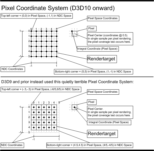
Direct3d 11 3 Functional Specification
A System Resource Flow is a simplified representation of a pathway or network pattern usually depicted graphically as a connector ie a line with possible amplifying information.
. In addition to this diagram a. Internodal Intranodal and Intrasystem system component. This system interface represents the requirements to exchange data between DCPDS and DCPDS.
Use Createlys easy online diagram editor to edit this diagram collaborate with others and export results to. 1 short forms of System Interface DiagramAbbreviation for System Interface. The interface block diagram is a traditional systems engineering block-and-line diagram representing the logical interfaces that connect components within a system or system.
Use Createlys easy online diagram editor to edit this diagram collaborate with others and export results to multiple. The purpose of Block Definition Diagrams is to specify system static structures that be used for Control Objects Data Objects and Interface Objects. In UML modeling interfaces are model elements that define sets of operations that other model elements such as classes or components must implement.
Interface diagrams can be created for composite interfaces which are defined in Interface Library section of Solution Documentation. 11 System Interface Diagrams job vacancies in Chennai Oman Singapore Kuwait Uae Bahrain Malaysia Indonesia Thailand Vietnam Philippines - Apply latest System Interface Diagrams job. New System Interface Diagram.
The entire software system is shown as a single process. An implementing model element. A system context diagram represents all external entities that may interact with a system.
How to abbreviate System Interface Diagram. These perspectives are described. Needed to connect a specific type of signal interface to a system.
Such a diagram pictures the system at. Using the drawing tools libraries of vector objects. ConceptDraw DIAGRAM extended with Windows 8 User Interface solution from the Software Development area is the best gui software.
System Interface - System. When properly applied See Usage Notes. The N 2 chart also referred to as N 2 diagram N-squared diagram or N-squared chart is a diagram in the shape of a matrix representing functional or physical interfaces between.
A diagram showing the connections line terminations etc. This system interface represents the requirements to exchange data between USXPORTS and FoS External Systems. System Interface Diagram Abbreviation.

Interface Design
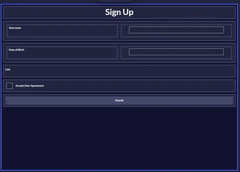
The User Interface Diagram Codebots

4 20ma Transmitter Test Board Project Circuit Cellar

Microsoft Windows 11 Features New Look Interface And A Whole Lot More B H Explora

An Inside Look At Oif S Common Electrical I O Project Edn

Systems Technician Resume Samples Qwikresume

Direct Dynamics Simulations Of Fragmentation Of A Zn Ii 2cys 2his Oligopeptide Comparison With Mass Spectrometry Collision Induced Dissociation The Journal Of Physical Chemistry A

Android 13 Changelog A Deep Dive By Mishaal Rahman

Treasury Enterprise Architecture Framework Wikiwand
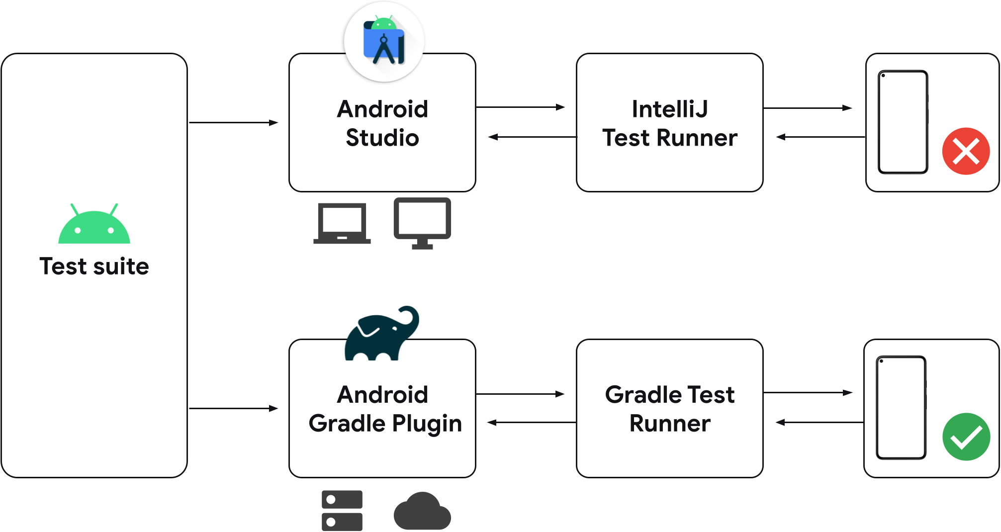
Past Releases Of Android Studio Android Developers
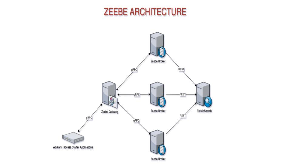
Page 14 Camunda

Mandatory Stages For Perfect Design Wireframes Mockups Prototypes
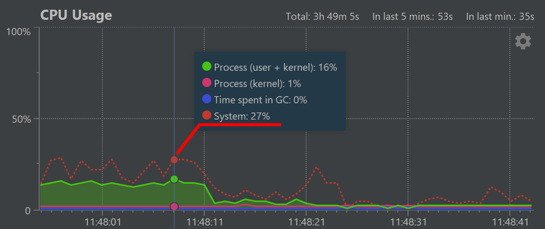
What S New In Java Profiler Yourkit

System Interface Diagram The Ea Pad
A Bim Lean Framework For Digitalisation Of Premanufacturing Phases In Offsite Construction Emerald Insight

Interface Design
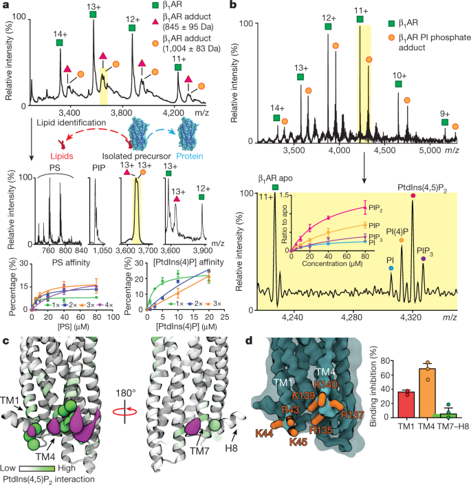
Ptdins 4 5 P2 Stabilizes Active States Of Gpcrs And Enhances Selectivity Of G Protein Coupling Nature